
Ready to build a fun and useful Arduino countdown timer? Then this project is perfect for you. In fact, you’ll create a 9-second timer that counts down on a 7-segment display and beeps when it finishes—all triggered by a single button press. Moreover, you’ll learn key electronics skills like BCD decoding, digital input handling, and alarm logic.
This guide gives you everything: a clear parts list, easy wiring steps, clean Arduino code, and testing tips. Therefore, whether you’re a student, hobbyist, or teacher, you can build this in under an hour. So, let’s turn your Arduino into a real-world countdown device!
Why Build an Arduino Countdown Timer with 7-Segment Display?
This project teaches multiple core concepts at once. First, it uses a push button as a digital input—so you learn how to read user actions. Second, it drives a 7-segment display using a 4511 BCD-to-7-segment decoder IC, which simplifies wiring and code. Third, it adds sound feedback with a buzzer, making the system feel complete and interactive.
Additionally, the countdown logic uses real-time delays, which helps you understand timing in embedded systems. As a result, you gain hands-on experience with inputs, outputs, displays, and alerts—all in one compact circuit. Furthermore, this setup mimics real devices like kitchen timers, game clocks, or lab equipment.
Best of all, it’s beginner-friendly. You don’t need complex libraries or sensors. Just basic components, simple code, and clear results. So, it’s an ideal first step into practical Arduino projects.
Essential Components for Arduino 7-Segment Countdown Timer
Gather these parts before you start. First, you need an Arduino Uno or any compatible board. Second, get a common cathode 7-segment display—make sure it’s common cathode, not common anode. Third, add a 4511 BCD-to-7-segment decoder IC. This chip converts binary numbers into readable digits automatically.
Next, include a buzzer—either active or passive works. Then, grab a momentary push button and a 10kΩ resistor for the button’s pull-up circuit. Also, prepare a breadboard and jumper wires for clean, reusable connections. Finally, use a standard USB cable to power and program your Arduino.
Optionally, you can use the Arduino’s internal pull-up resistor instead of the external 10kΩ one—but we’ll show both methods. Either way, the button will reliably start the countdown without false triggers.
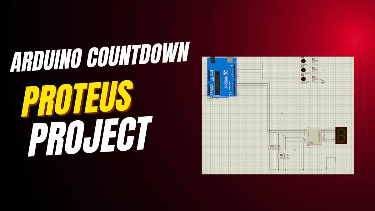
How to Wire the Arduino Countdown Timer Circuit
Start by connecting the 4511 IC. Link its BCD input pins—A, B, C, D—to Arduino digital pins 4, 5, 6, and 7. Note: the code uses pins in reverse order (D=7, C=6, B=5, A=4), so match them carefully. Then, connect the 4511’s output pins (a through g) to the matching segments on your 7-segment display.
After that, join the common cathode pin of the display directly to Arduino GND. This is critical—common cathode displays only work when the cathode is grounded. Next, wire the buzzer: connect its positive lead to Arduino pin 8 and the negative lead to GND.
Now, set up the push button. Connect one side of the button to Arduino pin 9. Connect the other side to GND. Then, place a 10kΩ resistor between pin 9 and the 5V rail. This pull-up resistor ensures the pin reads HIGH when the button is not pressed, and LOW when pressed.
💡 Tip: Double-check the 4511 datasheet for pin numbering. Some ICs label pins differently, and a wrong connection can cause garbled digits. Also, test the buzzer alone first to confirm it works.
Arduino Code for 7-Segment Countdown Timer with Buzzer
 // Pin Definitions
const int counterPins[] = {7, 6, 5, 4}; // Pins connected to 4511 IC (D, C, B, A)
const int buzzerPin = 8; // Buzzer connected to pin 8
const int startButtonPin = 9; // Start/Reset button
int counter = 9; // Start value for countdown

void setup() {
// Setup Counter Pins (4511 inputs)
for (int i = 0; i < 4; i++) {
pinMode(counterPins[i], OUTPUT);
}
// Setup Buzzer
pinMode(buzzerPin, OUTPUT);
digitalWrite(buzzerPin, LOW); // Buzzer off initially
// Setup Button (Internal pull-up is an alternative to the external resistor)
pinMode(startButtonPin, INPUT_PULLUP);
// Display initial counter value
updateCounter(counter);
}

void loop() {
// Wait for button press (LOW signal when using pull-up) to start countdown
if (digitalRead(startButtonPin) == LOW) {
delay(200); // Debounce delay
countdown(counter); // Start countdown
}
}

// Update 4511 IC to display counter value on 7-segment
void updateCounter(int value) {
for (int i = 0; i < 4; i++) {
// Write the BCD bit value to the 4511 pin
digitalWrite(counterPins[i], (value >> i) & 0x01);
}
}

// Countdown logic
void countdown(int startValue) {
counter = startValue;
while (counter >= 0) {
updateCounter(counter);
delay(1000); // Wait 1 second
counter--;
}
// Reset counter value for next run and trigger alarm
counter = startValue;
activateAlarm();
updateCounter(counter); // Display the starting value again
}

// Activate alarm (buzzer)
void activateAlarm() {
for (int i = 0; i < 5; i++) { // Buzzer beeps 5 times
digitalWrite(buzzerPin, HIGH);
delay(200);
digitalWrite(buzzerPin, LOW);
delay(200);
}
}
How the Arduino Countdown Timer Code Works
Let’s break it down step by step. First, the counterPins array holds the Arduino pins linked to the 4511 IC. The order matches BCD bit positions: pin 4 = A (LSB), pin 5 = B, pin 6 = C, pin 7 = D (MSB). This lets the updateCounter() function send the right binary pattern.
In setup(), all counter pins become outputs. The buzzer starts off. The button pin uses INPUT_PULLUP mode, which activates the Arduino’s internal pull-up resistor—so you don’t strictly need the external 10kΩ resistor (though it’s still good practice). Then, the display shows “9” right away.
In loop(), the code waits for the button press. When the button is pressed, digitalRead() returns LOW (because the pin connects to GND). A 200ms delay prevents bounce—so one press doesn’t trigger multiple starts. Then, countdown(9) runs.
Inside countdown(), the timer counts from 9 to 0, updating the display every second. Once it hits 0, it calls activateAlarm(). This function turns the buzzer on and off five times, creating a clear “beep-beep-beep” alert. Finally, it resets the display to “9” and waits for the next button press.
Step-by-Step Testing Guide for Your Countdown Timer
After uploading the code, test your system. First, the 7-segment display should show “9” immediately. If it shows nothing or a weird symbol, check the 4511 wiring and confirm the display is common cathode.
Next, press the button. The display must count down: 9, 8, 7… all the way to 0, with one-second intervals. If it skips numbers or freezes, verify your delay(1000) isn’t interrupted and that power is stable.
When it reaches 0, the buzzer should beep five times. If it stays silent, check the buzzer polarity and pin 8 connection. Also, ensure the buzzer isn’t a passive type requiring a tone() function—but most basic buzzers work with simple HIGH/LOW signals.
Finally, after the alarm, the display should return to “9” and wait for another press. This makes the system reusable without resetting the Arduino.
Common Issues and Quick Fixes
If the display shows “8” constantly, the 4511 isn’t getting BCD signals. Check that Arduino pins 4–7 are set as OUTPUT and wired correctly. Also, ensure the IC has 5V power and GND.
If the timer starts automatically without pressing the button, your pull-up isn’t working. Either add the 10kΩ resistor between pin 9 and 5V, or keep INPUT_PULLUP but verify the button connects pin 9 to GND only when pressed.
What if the buzzer beeps nonstop? Then the activateAlarm() function might be stuck in a loop. But in this code, it runs only once per countdown. So, check for wiring shorts or a faulty buzzer.
Lastly, if digits look wrong (e.g., “6” shows as “b”), the segment wires between the 4511 and display are swapped. Refer to your display’s datasheet and match segment labels (a, b, c…) exactly.
How to Upgrade Your Arduino Countdown Timer
Once it works, try these upgrades. First, add a potentiometer to set the countdown time. Read its analog value and map it to 1–60 seconds. This turns your timer into a customizable kitchen or study tool.
Second, replace delay() with millis() for non-blocking code. This lets you add features like a pause button or LED indicators without freezing the timer. For example, an LED could flash during countdown.
Third, use two 7-segment displays for two-digit timing (e.g., 30 seconds). You’ll need two 4511 ICs or a multiplexing technique—but it’s a great next challenge. Also, you could log countdown events to an SD card for tracking.
Moreover, connect it to a relay to control real devices—like turning off a lamp after 10 minutes. In this way, your simple timer becomes part of a smart home system.
Why This Project Is Perfect for Arduino Beginners
This countdown timer uses only digital I/O—no complex math, no external libraries, no wireless modules. Therefore, it’s easy to understand and debug. You see immediate visual and audio feedback, which builds confidence fast.
Additionally, every component has a clear purpose. The button starts action, the display shows time, the buzzer gives alert, and the 4511 simplifies the display wiring. As a result, you learn without feeling overwhelmed.
Teachers love this project for classrooms because it’s safe, affordable, and engaging. Students enjoy the “game-like” feel of pressing a button and watching the timer run. So, it’s both educational and fun.
Final Thoughts: Build, Learn, and Create More
This Arduino countdown timer proves that powerful learning comes from simple circuits. You’ve handled inputs, outputs, timing, decoding, and sound—all in one small project. Now, you’re ready for bigger challenges.
So, gather your parts, follow the steps, and press that button. In just minutes, you’ll have a working timer that beeps, counts, and responds to you. Then, start imagining your own versions—because every great inventor starts with a countdown.


Leave a Reply