
5 Simple Arduino Projects for Beginners: Learn Electronics Step by Step
Starting with Arduino can feel overwhelming—but it doesn’t have to be. In fact, with the right beginner-friendly projects, you’ll quickly grasp core concepts like input, output, sensors, and programming logic. Moreover, these hands-on experiments build confidence while teaching real-world skills. Therefore, we’ve curated five simple Arduino projects for beginners that use common components, clear code, and easy wiring. Each one includes a pin configuration table, circuit explanation, and ready-to-upload code—so you can learn by doing.
Why These Arduino Projects Are Perfect for Absolute Beginners
These projects focus on foundational electronics principles without unnecessary complexity. First, they use only the Arduino Uno—a widely available, beginner-friendly board. Second, every component is affordable and easy to find online or in local stores. Third, the code avoids advanced libraries or obscure functions. As a result, you’ll understand every line you upload. Above all, each project introduces one new concept at a time—so learning feels natural, not forced.
Project 1: LED Brightness Control Using a Potentiometer
Master Analog Input and PWM Output with This Classic Project
This first project teaches you how to read analog signals and control power output—two essential skills in embedded systems. Specifically, you’ll use a potentiometer to adjust LED brightness in real time. Because the potentiometer acts like a variable voltage divider, it sends a smooth analog signal to the Arduino. Then, the microcontroller converts that signal into a PWM (Pulse Width Modulation) output to dim or brighten the LED. Consequently, you’ll see how analog input directly influences digital-like output behavior.
Circuit Setup and Pin Configuration
Wiring this project takes just minutes. Connect the potentiometer’s middle pin to analog input A0. Then, link the LED’s anode (long leg) to digital pin 6 through a 220Ω resistor. Finally, ground both components properly. Below is the complete pin mapping:
| Component | Arduino Pin | Function |
|---|---|---|
| LED | D6 | PWM output to control brightness |
| Potentiometer | A0 | Analog input for voltage reading |
Arduino Code for Smooth LED Dimming
int led_pin = 6;
int pot_pin = A0;
int output;
int led_value;

void setup() {
  pinMode(led_pin, OUTPUT);
}

void loop() {
  output = analogRead(pot_pin);
  led_value = map(output, 0, 1023, 0, 255);
  analogWrite(led_pin, led_value);
  delay(1);
}
This code reads the potentiometer value (0–1023) and maps it to a PWM range (0–255). Then, it writes that value to the LED pin. Since the loop runs continuously, the brightness updates instantly as you turn the knob. Furthermore, the tiny 1-millisecond delay ensures smooth responsiveness without overloading the processor.
Project 2: Motion Detection with a PIR Sensor and LED
Build a Basic Security System Using Digital Input
Next, explore digital sensing with a Passive Infrared (PIR) motion sensor. When the sensor detects body heat movement, it sends a HIGH signal to the Arduino. In response, the board lights an LED and prints a message to the Serial Monitor. This project introduces event-based programming—where actions trigger only under specific conditions. Additionally, it demonstrates how to avoid repeated messages using a state-tracking variable.
Wiring Guide and Pin Layout
Connect the PIR sensor’s output pin to digital pin 2. Then, attach an LED to pin 13 (which has a built-in resistor on most Uno boards). Make sure VCC and GND go to 5V and ground, respectively. Here’s the official pin configuration:
| Component | Arduino Pin | Function |
|---|---|---|
| PIR Sensor | D2 | Detects human motion via infrared |
| LED | D13 | Visual alert when motion is detected |
Arduino Code for Reliable Motion Alerts
int led = 13;
int sensor = 2;
int state = LOW;
int val = 0;

void setup() {
  pinMode(led, OUTPUT);
  pinMode(sensor, INPUT);
  Serial.begin(9600);
}

void loop() {
  val = digitalRead(sensor);
  if (val == HIGH) {
    digitalWrite(led, HIGH);
    delay(500);
    if (state == LOW) {
      Serial.println("Motion detected!");
      state = HIGH;
    }
  } else {
    digitalWrite(led, LOW);
    delay(500);
    if (state == HIGH) {
      Serial.println("Motion stopped!");
      state = LOW;
    }
  }
}
The state variable prevents the Serial Monitor from flooding with repeated “Motion detected!” lines. Instead, it prints the message only when motion starts or stops. Meanwhile, the 500ms delay stabilizes the sensor’s output—since PIR modules often need a brief cooldown period after triggering.
Project 3: Arduino Voltmeter with I2C LCD Display
Measure and Display Voltage in Real Time
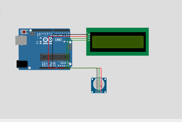
Now, combine analog reading with visual output. This Arduino voltmeter reads an external voltage (up to 5V) and shows the result on a 16×2 LCD screen. Because it uses I2C communication, it saves valuable pins—only two wires (SDA and SCL) connect the display. Therefore, this project teaches both analog-to-digital conversion and efficient peripheral interfacing.
Pin Connections for Minimal Wiring
Plug the I2C LCD module into the Arduino’s SDA (A4) and SCL (A5) pins—no extra resistors needed. Then, connect your voltage source (e.g., a battery or potentiometer) to analog pin A3. The table below summarizes the setup:
| Component | Arduino Pin | Function |
|---|---|---|
| LCD (I2C) | SDA, SCL | I2C data and clock lines |
| Voltage Input | A3 | Reads analog voltage (0–5V) |
Arduino Code for Accurate Voltage Readings
#include <Wire.h>
#include <LiquidCrystal_I2C.h>

LiquidCrystal_I2C lcd(0x27,16,2);
int Vpin = A3;
float voltage;
float volts;

void setup() {
  Serial.begin(9600);
  lcd.init();
  lcd.backlight();
}

void loop() {
  voltage = analogRead(Vpin);
  volts = voltage / 1023 * 5.0;
  Serial.println(volts);
  lcd.print("Voltage = ");
  lcd.print(volts);
  delay(500);
  lcd.clear();
}
The code converts the raw analog reading (0–1023) into volts using the formula: volts = (reading / 1023) * 5.0. Then, it prints the value to both the Serial Monitor and the LCD. Note that the display clears every 500ms to prevent text overlap—ensuring clean, readable output.
Project 4: Ultrasonic Distance Sensor with LED Warning
Detect Objects and Trigger Alerts Automatically
This project uses an HC-SR04 ultrasonic sensor to measure distance—just like a parking assist system. When an object comes within 50 cm, an LED turns on as a warning. As a result, you’ll learn how to calculate physical distance from time-of-flight data. Additionally, you’ll practice using pulseIn(), a key function for timing-based sensors.
Pin Configuration for HC-SR04 and Indicator LED
Connect the sensor’s Trig pin to D9 and Echo to D10. Then, wire the LED to D8 with a current-limiting resistor. The full pin map is shown below:
| Component | Arduino Pin | Function |
|---|---|---|
| Trig Pin (Sensor) | D9 | Sends ultrasonic pulse |
| Echo Pin (Sensor) | D10 | Receives reflected signal |
| LED Indicator | D8 | Warns when object is too close |
Arduino Code for Real-Time Distance Monitoring
const int trigPin = 9;
const int echoPin = 10;
const int ledPin = 8;
const int movementThreshold = 50;
void setup() {
  pinMode(trigPin, OUTPUT);
  pinMode(echoPin, INPUT);
  pinMode(ledPin, OUTPUT);
  Serial.begin(9600);
  Serial.println("Starting distance sensor...");
}
void loop() {
  digitalWrite(trigPin, LOW);
  delayMicroseconds(2);
  digitalWrite(trigPin, HIGH);
  delayMicroseconds(10);
  digitalWrite(trigPin, LOW);

  long duration = pulseIn(echoPin, HIGH);
  int distance = duration * 0.034 / 2;

  Serial.print("Distance: ");
  Serial.print(distance);
  Serial.println(" cm");
  if (distance > 0 && distance <= movementThreshold) {
    Serial.println("Object detected. Turning LED on.");
    digitalWrite(ledPin, HIGH);
  } else {
    Serial.println("No object detected. Turning LED off.");
    digitalWrite(ledPin, LOW);
  }
  delay(200);
}
The sensor calculates distance using the speed of sound (0.034 cm/µs). By measuring how long the echo takes to return, it computes: distance = (duration × 0.034) / 2. The division by 2 accounts for the round-trip travel. Meanwhile, the 200ms delay prevents sensor overload and ensures stable readings.
Project 5: 7-Segment Display Counter with Push Button
Control Individual Display Segments Using Digital Outputs
Finally, dive into multi-pin digital control with a 7-segment display. Each segment (a–g) connects to a separate Arduino pin. When you press a button, the counter increments from 0 to 9 and loops back. This project teaches binary logic, bit manipulation, and debouncing basics—all while creating a satisfying visual result.
Wiring the 7-Segment Display and Button
Connect segments a through g to digital pins 2–8. Then, wire a push button between A0 and ground, using the internal pull-up resistor. The pin layout is as follows:
| Component | Arduino Pin | Function |
|---|---|---|
| 7-Segment Display (a–g) | D2–D8 | Controls each LED segment |
| Push Button | A0 | Input to increment counter |
Arduino Code for Segment-by-Segment Control
int segmentPins[] = {2, 3, 4, 5, 6, 7, 8};
int buttonPins = A0;
byte numbers[10] = {
  0x3F, 0x06, 0x5B, 0x4F, 0x66, 0x6D,
  0x7D, 0x07, 0x7F, 0x6F
};
int counter = 0;
void setup() {
  for (int i = 0; i < 7; i++) {
    pinMode(segmentPins[i], OUTPUT);
  }
  pinMode(buttonPins, INPUT_PULLUP);
}
void loop() {
  if(digitalRead(buttonPins) == LOW){
    displayNumber(counter);
    counter = (counter + 1) % 10;
    delay(300);
  }
}
void displayNumber(int num) {
  for (int i = 0; i < 7; i++) {
    digitalWrite(segmentPins[i], (numbers[num] >> i) & 1);
  }
}
The numbers[] array stores hex values that represent which segments light up for each digit (0–9). The displayNumber() function shifts bits to control each pin individually. Also, note the use of INPUT_PULLUP—this eliminates the need for an external resistor and ensures a clean HIGH/LOW signal when the button is pressed.
Why These Projects Build a Strong Arduino Foundation
Together, these five projects cover the core pillars of Arduino development. First, you handle analog and digital inputs—from potentiometers to motion sensors. Second, you generate outputs like PWM signals, LED states, and display text. Third, you learn timing, state management, and serial debugging. Consequently, you’ll be ready to tackle more advanced builds like smart home systems, weather stations, or robotics.
Next Steps After Completing These Beginner Arduino Projects
Once you’ve built all five, consider adding enhancements. For example, replace the LED in Project 2 with a buzzer for audible alerts. Or, connect Project 4’s distance sensor to a servo to create an automatic door. Moreover, you can merge Project 3 and Project 1 into a light-controlled voltmeter. The possibilities grow as your confidence does.
Final Thoughts: Start Small, Learn Fast, Build Big
These simple Arduino projects for beginners prove that powerful learning comes from small, focused experiments. Each one delivers immediate feedback, clear outcomes, and reusable code patterns. Therefore, don’t rush—build them one at a time, understand the logic, and tweak the parameters. Before long, you’ll design your own circuits, troubleshoot like a pro, and join the global community of makers shaping the future with microcontrollers.


Leave a Reply