
Smart Parking System with Arduino: Real-Time Monitoring and Automated Gate Control
Imagine a parking lot that automatically detects available spots, opens gates only when space is free, and shows real-time occupancy on a display—all powered by an Arduino. This smart parking system does exactly that. Moreover, it uses minimal pins thanks to a clever 74HC165 shift register. Consequently, hobbyists and engineers alike can build scalable, efficient parking solutions without overwhelming the microcontroller.
Why Build a Smart Parking System with Arduino?
Urban parking is increasingly chaotic. Therefore, automating basic functions like entry control and spot monitoring saves time and reduces congestion. Additionally, this Arduino-based smart parking project offers hands-on experience with sensors, servos, and data display—all while using affordable, widely available components. Above all, it lays the foundation for IoT integration, enabling remote monitoring in the future.
Key Features of This Arduino Smart Parking Project
This system isn’t just functional—it’s intelligent. First, it monitors up to four parking spots in real time. Second, it controls entry and exit gates using servo motors. Third, it provides instant visual feedback via LEDs and an LCD. Finally, it maximizes pin efficiency through a 74HC165 shift register. As a result, you get a compact, responsive, and expandable design.
How the Smart Parking System Works: Step-by-Step Workflow
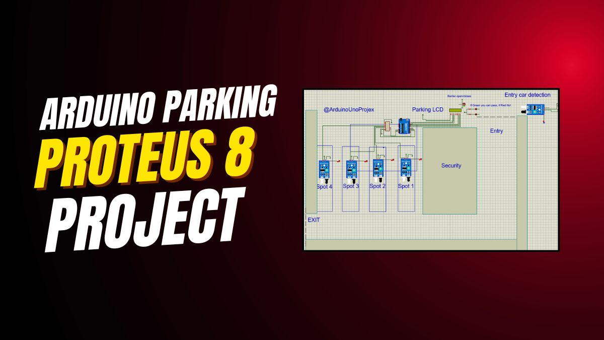
Real-Time Parking Spot Monitoring Using IR Sensors
Four IR sensors detect whether each parking spot is occupied. Instead of connecting each sensor directly to the Arduino—which would consume four precious I/O pins—the project uses a 74HC165 parallel-in, serial-out shift register. Accordingly, all four sensor states feed into just three Arduino pins: SH_LD (A1), CLK (3), and SO (2). This approach not only saves pins but also simplifies wiring and improves scalability.
Automated Entry Gate Control Based on Availability
When a vehicle approaches the entrance, an entry IR sensor (pin 4) triggers. If at least one parking spot is free, the green LED lights up, and the entry gate servo (on A2) rotates to 90 degrees—opening the barrier. After a half-second delay, the servo returns to 0 degrees, closing the gate. However, if the lot is full, the red LED blinks instead, and the gate stays shut. Thus, access is granted only when space exists.
Seamless Exit Gate Operation
Similarly, when a car leaves, the exit IR sensor (pin 5) detects motion. Immediately, the exit gate servo (on A3) opens for 500 milliseconds, allowing the vehicle to pass. Unlike the entry gate, the exit gate operates regardless of occupancy—because exiting always frees up space. Therefore, the system prioritizes smooth egress without unnecessary delays.
Live LCD Display with Intuitive Symbols
The 16×2 LCD provides clear, real-time status updates. Line one shows spot numbers: “1|2|3|4|”. Line two uses simple symbols: “X” means occupied, and “Y” means free. For example, “Y|X|Y|X|” indicates spots 1 and 3 are available. This visual language ensures even non-technical users understand availability at a glance. Moreover, the display refreshes every 500 milliseconds for up-to-date accuracy.
Complete Hardware List for Arduino Smart Parking System
Building this project requires only common, low-cost components. Specifically, you’ll need:
- Arduino Uno Board
- 74HC165 Shift Register IC
- Two Servo Motors (for entry and exit gates)
- Six IR Sensors (2 for entry/exit detection + 4 for parking spots)
- 16×2 LCD Display (with standard HD44780 controller)
- One Green LED and One Red LED
- 220Ω Resistors (for LEDs)
- Breadboard and Jumper Wires
Pin Connections: Wiring Diagram Simplified
All connections follow a logical, easy-to-trace layout. First, the LCD uses pins 13 through 8 for data and control. Second, the 74HC165 connects via SH_LD to A1, CLK to digital pin 3, and SO to pin 2. Third, LEDs go to pins 7 (green) and 6 (red). Fourth, entry and exit IR sensors link to pins 4 and 5. Finally, servos attach to analog pins A2 (entry) and A3 (exit). Because of this organization, troubleshooting becomes straightforward.
Full Arduino Code for Smart Parking System
The code efficiently handles sensor reading, logic decisions, and output control. Below is the complete, ready-to-upload sketch:
#include <Wire.h>
#include <LiquidCrystal.h>
#include <Servo.h>

// LCD pins
LiquidCrystal lcd(13, 12, 11, 10, 9, 8);

// 74HC165 pins
#define SH_LD A1
#define CLK 3
#define SO 2

#define green 7
#define red 6

// IR sensors
#define ENTRY_SENSOR 4
#define EXIT_SENSOR 5

// Servo motors
Servo entryGateServo;
Servo exitGateServo;

const int NUM_SPOTS = 4;
bool spots[NUM_SPOTS];
int freeSpots = NUM_SPOTS;

void setup() {
  lcd.begin(16, 2);
  lcd.clear();

  entryGateServo.attach(A2);
  exitGateServo.attach(A3);
  entryGateServo.write(0);
  exitGateServo.write(0);

  pinMode(SH_LD, OUTPUT);
  pinMode(CLK, OUTPUT);
  pinMode(SO, INPUT);
  pinMode(green, OUTPUT);
  pinMode(red, OUTPUT);
  pinMode(ENTRY_SENSOR, INPUT);
  pinMode(EXIT_SENSOR, INPUT);

  digitalWrite(green, LOW);
  digitalWrite(red, LOW);
  Serial.begin(9600);
}

void loop() {
  readShiftRegister(spots);

  freeSpots = 0;
  for (int i = 0; i < NUM_SPOTS; i++) {
    if (!spots[i]) freeSpots++;
  }

  // Entry gate logic
  if (digitalRead(ENTRY_SENSOR) == HIGH) {
    if (freeSpots > 0) {
      digitalWrite(green, HIGH);
      entryGateServo.write(90);
      delay(500);
      entryGateServo.write(0);
      digitalWrite(green, LOW);
    } else {
      digitalWrite(red, HIGH);
      delay(500);
      digitalWrite(red, LOW);
    }
  }

  // Exit gate logic
  if (digitalRead(EXIT_SENSOR) == HIGH) {
    exitGateServo.write(90);
    delay(500);
    exitGateServo.write(0);
  }

  // LCD update
  lcd.clear();
  lcd.setCursor(0, 0);
  lcd.print("1|2|3|4|");
  lcd.setCursor(0, 1);
  for (int i = 0; i < NUM_SPOTS; i++) {
    lcd.print(spots[i] ? "X|" : "Y|");
  }

  delay(500);
}

void readShiftRegister(bool ar[NUM_SPOTS]) {
  digitalWrite(SH_LD, LOW);
  delayMicroseconds(5);
  digitalWrite(SH_LD, HIGH);

  for (int i = 0; i < NUM_SPOTS; i++) {
    digitalWrite(CLK, LOW);
    delayMicroseconds(5);
    ar[i] = digitalRead(SO);
    digitalWrite(CLK, HIGH);
    delayMicroseconds(5);
  }
}
Code Breakdown: How Each Function Works
The setup() function initializes the LCD, attaches servos, configures pin modes, and starts serial communication for debugging. Meanwhile, the loop() function continuously reads sensor data, counts free spots, processes entry/exit logic, and refreshes the LCD. Crucially, the custom readShiftRegister() function captures all four parking spot states in sequence using clock pulses. Because of this modular design, modifying the number of spots later becomes simple.
Practical Applications of This Smart Parking Project
Smart Parking Lots for Residential and Commercial Use
This system is ideal for apartment complexes, office buildings, or small shopping centers. By automating entry based on availability, it prevents overcrowding and eliminates manual oversight. Furthermore, the visual feedback reduces driver frustration—no more circling endlessly for a spot.
IoT-Ready Foundation for Cloud Monitoring
Although this version runs locally, it’s designed for future expansion. For instance, you can add an ESP8266 or ESP32 module to send occupancy data to a web dashboard. Consequently, users could check parking availability via a mobile app before arriving. In fact, integrating with platforms like Blynk or ThingSpeak takes only a few extra lines of code.
Scalable Design Using Cascaded Shift Registers
Need to monitor 8, 12, or even 16 spots? Simply cascade additional 74HC165 ICs. Each new chip adds eight inputs while using the same three Arduino pins. Therefore, the system scales almost infinitely without taxing the microcontroller. This makes it perfect for larger installations or educational demonstrations of digital logic.
Tips for Building and Troubleshooting Your System
Calibrate IR Sensors for Reliable Detection
IR sensors can be sensitive to ambient light. To ensure accuracy, test them in your actual parking environment. Adjust the potentiometer on each sensor module until it reliably detects a car’s undercarriage without false triggers. Additionally, mount sensors at a consistent height and angle for uniform performance.
Power Servos Separately to Avoid Resets
Servos draw significant current during movement. If powered directly from the Arduino’s 5V pin, they may cause voltage drops that reset the board. Instead, use an external 5V power supply for the servos, sharing a common ground with the Arduino. This simple step prevents erratic behavior and improves reliability.
Use Serial Monitor for Real-Time Debugging
The code includes Serial.begin(9600) but doesn’t print debug messages by default. However, you can add Serial.print() statements inside the loop to monitor sensor values, free spot counts, or gate actions. As a result, diagnosing issues becomes much faster during development.
Expand Your Skills: Related Arduino Projects to Try Next
Once you’ve mastered this smart parking system, consider these advanced challenges:
- IoT Parking Dashboard: Add Wi-Fi and publish data to a cloud platform.
- RFID-Based Access Control: Allow only authorized vehicles to enter.
- Ultrasonic Sensor Upgrade: Replace IR with HC-SR04 for more precise distance-based detection.
- Multi-Level Parking: Use multiple shift registers to manage several floors.
Each of these builds on core concepts from this project—sensor integration, actuator control, and efficient I/O management. Therefore, they provide natural next steps in your embedded systems journey.
Conclusion: Build, Learn, and Automate with Confidence
This Arduino smart parking system proves that powerful automation doesn’t require complex hardware. By combining IR sensors, servos, an LCD, and a shift register, you create a responsive, intelligent solution that mimics real-world systems. Whether you’re a student, hobbyist, or educator, this project delivers practical experience in embedded logic, real-time decision-making, and hardware optimization. So gather your components, upload the code, and watch your parking lot come alive—with intelligence.
Don’t stop here. Experiment, expand, and share your improvements. The future of smart cities starts with projects like this—one Arduino at a time.


Leave a Reply